3D Match Moving
Week 01: Nuke 3D and Camera Projection
During the first session of the module, we were introduced to the 3D workspace and tools in Nuke. We learnt how to add 3D objects, textures and cameras in the 3D workspace. We then explored texturing the objects, transforming them and animating cameras, and finally render out them as a 2D scene. Ultimately, we made a few camera projections and applied those techniques to 2D images. Camera projection techniques can transform a 2D matte painting into a 3D scene. Therefore, in camera projection techniques, An image is "projected" into 3D geometry through a camera.
.png)
Exercise 1: A basic 3D setup
This is a basic 3D set up with a few 3D nodes. All the elements in a 3D workspace can be combined with a Scene node - all the geometric objects, cameras, and lights. I animated the camera's 'translate' and 'rotate' attributes.
.png)
Final node graph.
.png)
Screen recording.
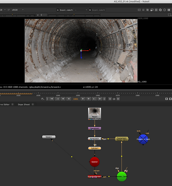
Exercise 2: Projecting a tunnel to a cylinder
Method #1:
Made a basic setup with Project3D, Cylinder, Scene, ScanlineRender, render cam and projection cam nodes. Note: rotate the cylinder to mimic the tunnel while the camera is going through it.

I scaled up the cylinder along the Y-axes to mimic the tunnel.

Final node graph.
.png)
Screen recording. Check out the workflow in the video above.
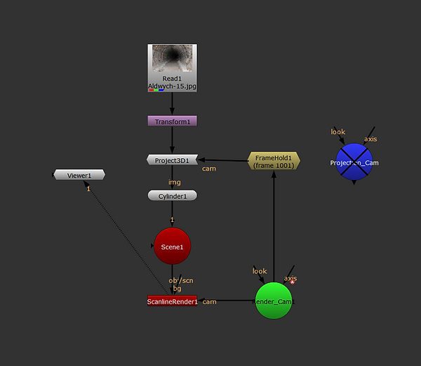
Method #2:
I used FrameHold instead of Projection Cam here.
Node graph.
.png)
Screen capture.
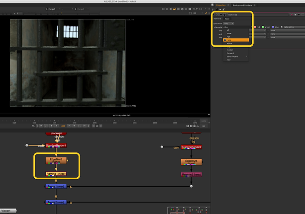
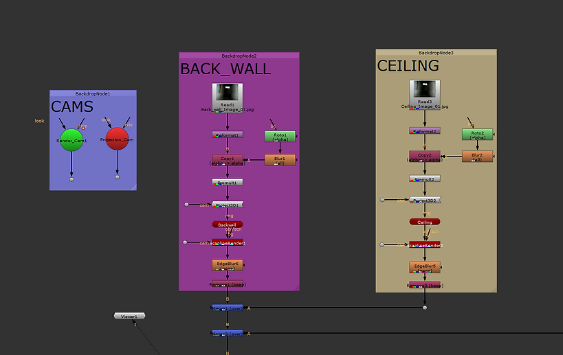
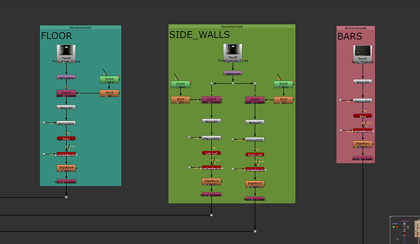
Exercise 2: Projecting different parts of an image to cards
This is an exciting and useful workflow and can be used to build a 3D Environment from a 2D Image
We have already set up render and projection cameras. Chose 'Fill' for resize type of the reformat node.

I started from the back wall, roto'ed it and used Project3D node for projection.


Projected various parts of the image to several cards, then moved them to build up the room.

Note: Set the number of samples to render per pixel, to produce motion blur and antialiasing.

Note: I used the Remove node to remove channels from the input clip, and make the rendering process smoother and faster.
.png)
.png)
.png)
Workflow (screen capture)
Render
Week 02: Nuke 3D Tracking
We looked at 3D Camera Tracking this week. 3D Match Moving, as previously discussed, is the process of mixing filmed sequences (live backplates) with CGI in such a way that they match one another. The goal is to transform live backplate footage into a 3D environment and simulate parallax movement in the scene. As a result, 3D Match Moving is the act of detecting a pattern in a set of pixels and following it across the screen. The programme then monitors points in order to create a three-dimensional camera and recreate the motions. Lens distortion will be one of the problems we will confront. Thus, we need to straighten out the curvature caused by the lens to do 3D tracking correctly.
Exercise 1
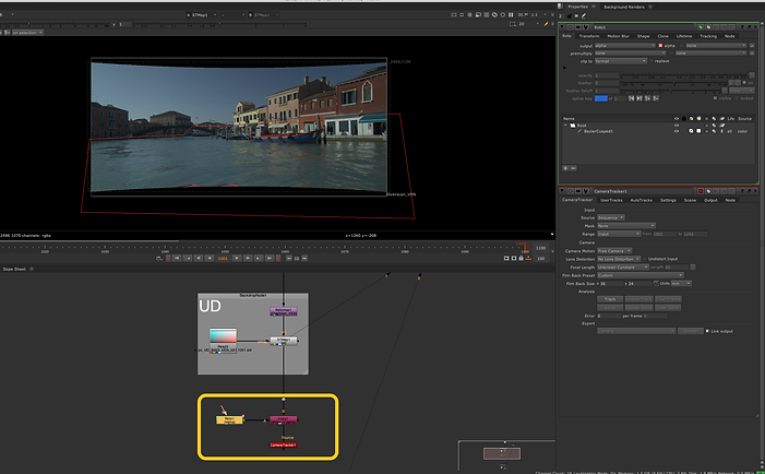
I first brought in a camera tracker node to track the scene. Water and the moving people are not suitable for tracking, so I roto'ed them out.

Turn on Preview Features in the camera tracker settings.

Increased the number of features to track in each frame.

Selected Source Alpha to apply the previously made mask (roto).

Hit Track to start tracking.

After tracking, we need to hit Solve to check the tracking quality.

Deleted the invalid tracks (amber and red marks)
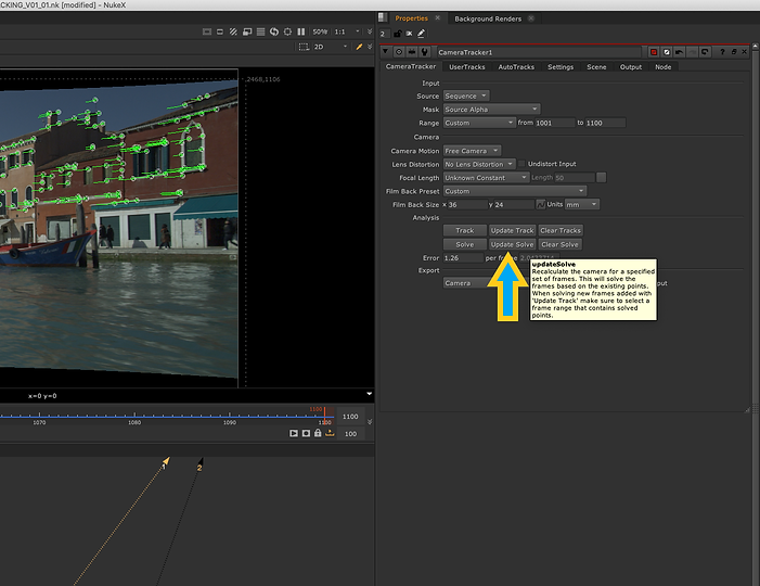
Update Solve to check the tracks again. We may need to do these steps again to delete all the invalid tracks.

In this stage, the Camera Tracker node created a scene, a camera tracker point cloud and camera nodes for me.
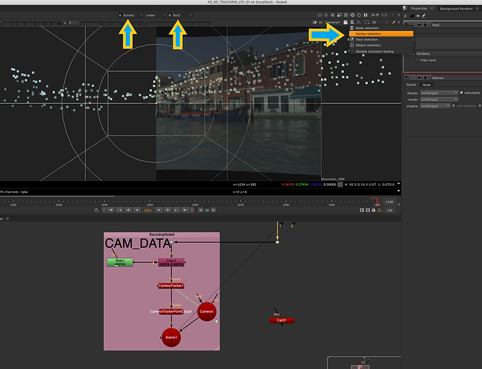
First pressed W on the keyboard to see two media in viewer. Next, reduced the opacity of the scene to be able to see dots. Finally, chose Vertex Selection to be able to select dots.

While the specific dots are selected, brought in a card and pressed Match Selection Points

I then tried to align the card with the dots.

Final result.

Node graph.
Exercise 2
In this exercise, instead of using a checkerboard card, we projected a patch to a card and snapped the card to a part of the scene using a camera tracker.

Node graph.
3D Clean up Script layout

Week 3: 3D Equalizer
We were introduced to 3D Equaliser this week. 3D Equaliser is one of the most powerful 3D tracking software, widely used by most of the major studios around the globe. During the session, we got our head around the software user interface and practised a few essential tracking workflows.
To simplify the way we interact with the software, we set up a bunch of shortcuts as below:
Tracking in 3DEquiliser (important steps and tips)

Don't forget to set the frame rate when importing your footage!
.png)
First things first, head to Playback -> Export Buffer Compression File if playback is slow. If you already have the buffer file, you need to import it.

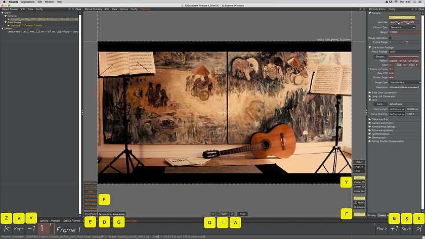
Set Filmback Width, then Pixel Aspect and finally Focal Length. Also, put an Identifier in the related field.
Ctrl-click to make a tracking point. When done, Alt-click to deselect the point. To reselect a point, Alt-drag around it. To gauge, press G. To track press T.

When a point goes out of the screen, the tracking process stops. This also happens when the image is so blurry. So we need to go to the relevant frame and make the tracking area smaller.

We may change the tracking mode of specific points to "Marker".

Adding more tracks helps us have a more accurate result.

3D Orientation veiw.

Activate Deviation Browser to be able to see the tracking quality.

Go to Calc -> Calc All From Scratch. You can also press Alt + C.
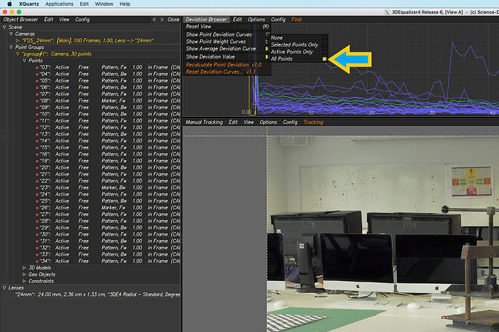
Tick the box for "All Points" to be able to see all tracking points in the deviation browser.
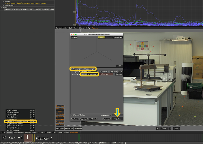
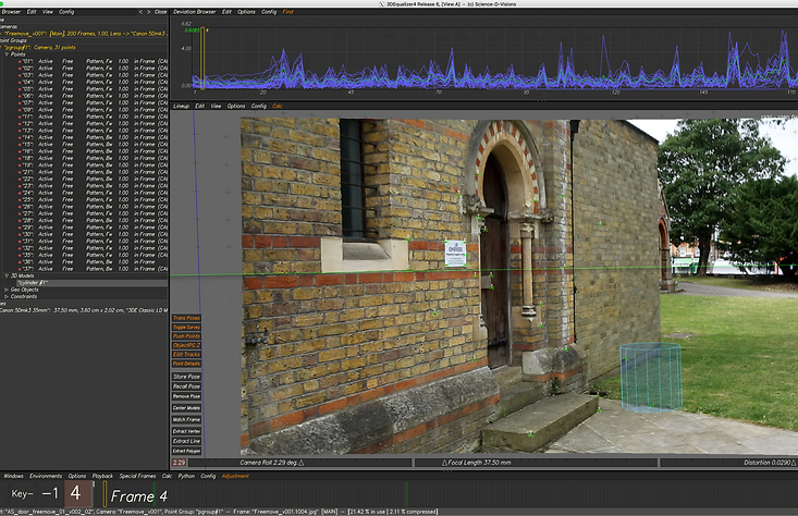
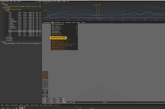
Bring up Parameter Adjustment Window and adjust the focal length.
.png)
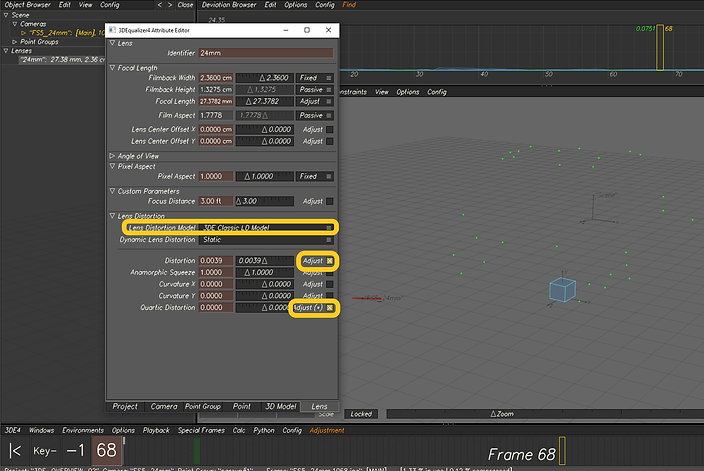
Double-click on the lens to open up the attribute editor. Then go to Lens Distortion and select 3DE Classic LD Model. Tick the boxes for Distortion and Quartic Distortion.
.png)
Then again head to Parameter Adjustment and this time press Adaptive All and then Adjust...
Screen capture
Week 04: Lenses and Cameras
We practised the previously learnt workflows of tracking in 3D Equaliser this week. Also, we looked at camera setting camera constraints, changing the camera's height according to the survey data, and creating distance constraints. So what we need to do is put the survey data into the 3D Equaliser to have better and more accurate tracking.
Survey data

Practice #1: Nodal shot (fixed camera position)
Setting camera constraint

In this scene, the camera only rotates, so its position is fixed. However, you can see that 3D Equaliser assumed that the camera had movement. We need to fix this!
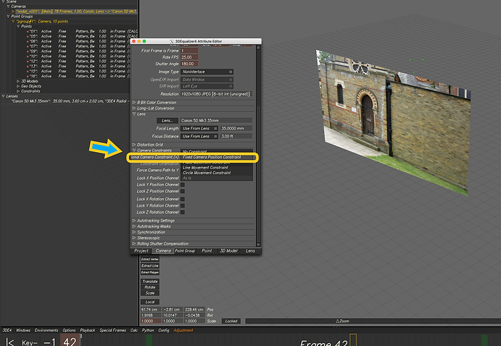
To fix that, we set up a camera constraint.

You can see that the camera is now fixed and has only rotation.
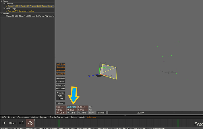
Changing camera's height
.png)
Creating distance constraint
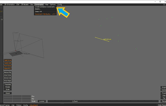.png)
Practice #2: Free shot (parallax view)
.png)
Selected the tracking points on the ground.
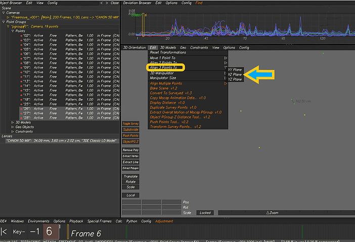.png)
Algined the points to XZ Plane so that all the points will be placed above the grid.
.png)
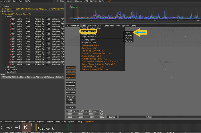
Selected one of the ground points and moved to to origin.
.png)
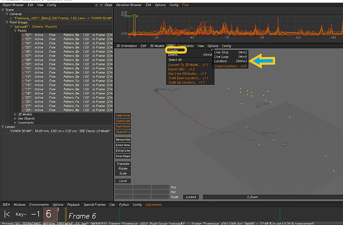
Created locators from all the points.
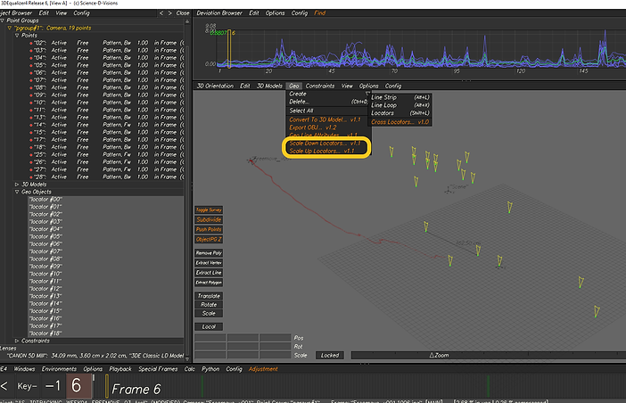.png)
Scaled up the locators for us to be able to clearly see them in the scene.
.png)
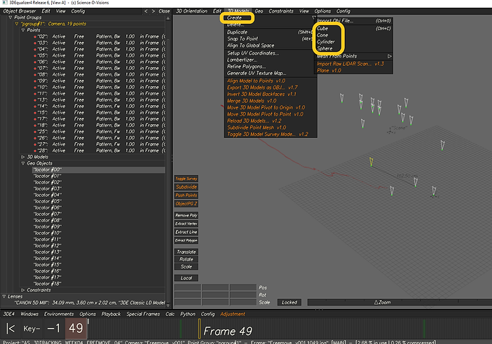
Made a cone to snap it to a locator positioned on the ground.
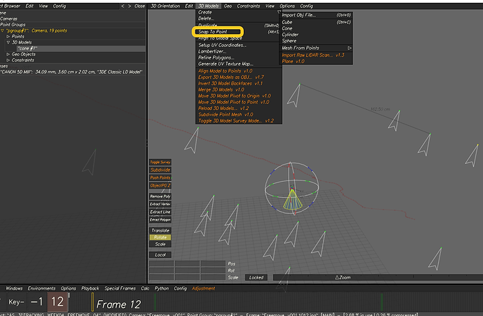.png)
Cone snapped to a ground locator.
.png)
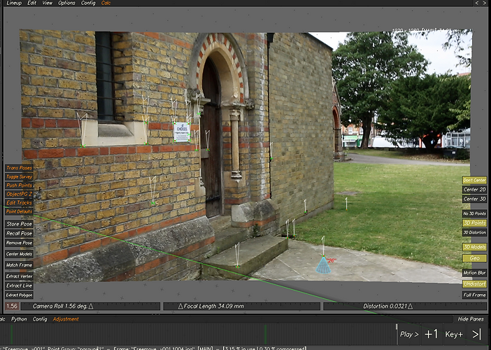
Result.
Screen capture
Week 05: 3DE Freeflow and Nuke
This week we learnt how to bake the scene in 3DE export out the assets to use them in Nuke. Overall, we export out the camera, locators, 3d objects and lens distortion and use a specific workflow for lens distortion in Nuke. As another exercise, we created a patch based on the information we brought into Nuke from 3DE.
3DE: Exporting assets for Nuke
Cintinuing from where I left off last week. I had a cylinder snapped to a point on the ground and many tracking points in the scene.

In order to export the assets from 3DE, I needed to bake the scene first.

Export Project: exports the camera. Browse the file and put it to MATCHMOVING -> CAMERA

Selected all the points, and created locators from them. Then chose all the locators and headed to Geo -> Export OBJ... Put the output file to MATCHMOVING -> GEO.

To export the lens distortion, I headed to File -> Export -> Export Nuke LD_3DE Lens Distortion Node. Put the exported file to MATCHMOVING -> UNDISTORT

Selected the cylinder and exported it by going to 3D Models -> Export Obj File... Put it to MATCHMOVING -> GEO
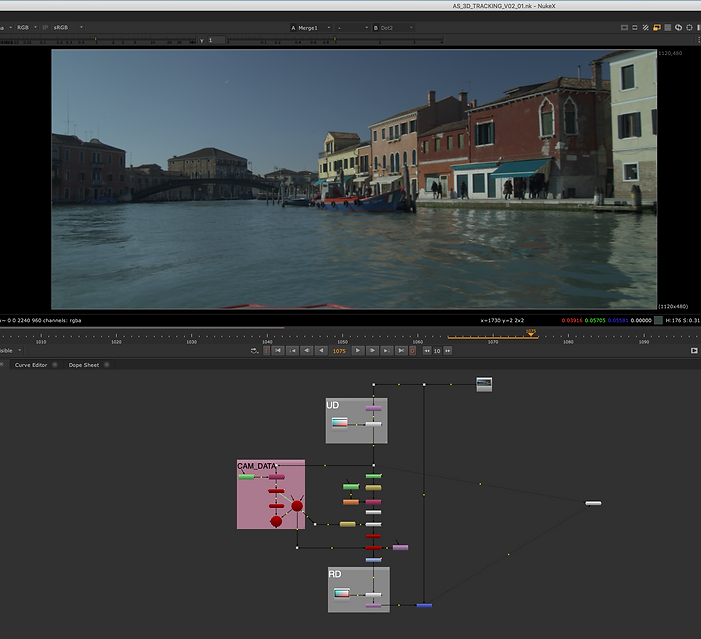
Nuke: using 3DE data

The camera output file dragged to Nuke.

I dragged and dropped all the 3DE exported files namely lens distortion, 3D object, camera and locators. I only kept the camera node and deleted other extra nodes for the camera.

Important: UD and RD should be set up as above.

Important: as I scaled up (for 1.1) the footage by Overscan (reformat) node, I need to multiply Horiz Aperture and Vert Aperture each in 1.1.

The nodes and setup I used to be able to see the cylinder and locators in the scene.

Here I wanted to use a patch and remove the text on the plate. I then needed to use 3DE data to track the plate.

Roto'ed the plate using the above nodes and set up.

Projected the roto to a card and aligned the card with the plate in 3D.
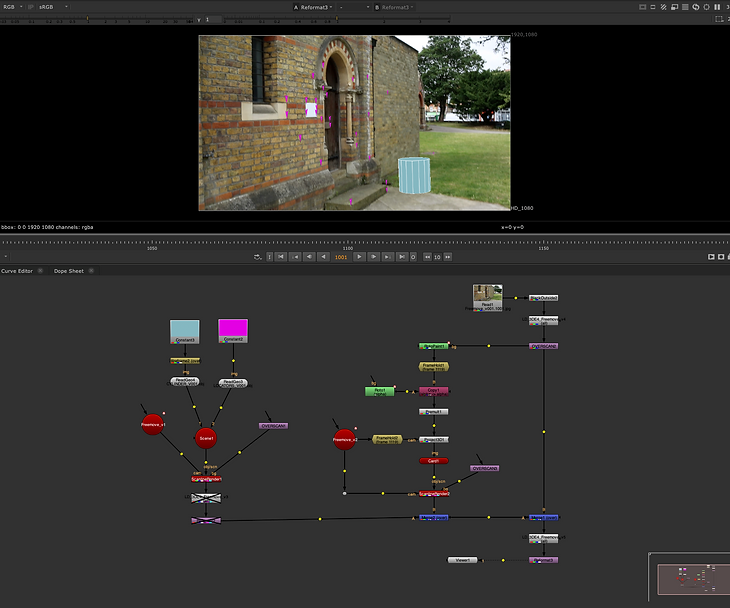
Result.

Node graph.
Week 06: Surveys
This week, we looked at how to set survey points within a scene. We learned how to use all the provided survey data and various measurements to track elements more precisely in our scene in 3DE.
Survey image

Using the measurements and making survey points

In the 3D Orientation view, go to Points Groups and R-click on Points to add new points.
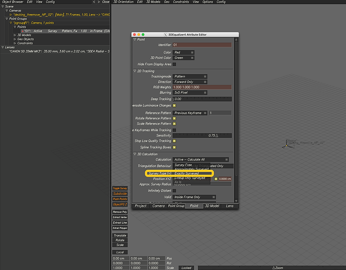
Select Exactly Surveyed for Survey Type.

Put the exact measurements in Position XYZ fields.

Go to Preferences to change the Regular Units to the unit you have your measurements in.

I first started to make survey points for the ground.

We can duplicate our survey points as above.

All the survey points made.

After making the survey points, it's time to track them. Simply select the point, then control-click on the corresponding area and track when on Manual Tracking. Head to the Image Controls Window to brighten up the scene so that we can see dark spots.

All points tracked.

As before, adjust the lens distortion.

Select Brute Force the lens distortion.

Select Adaptive All for focal length.
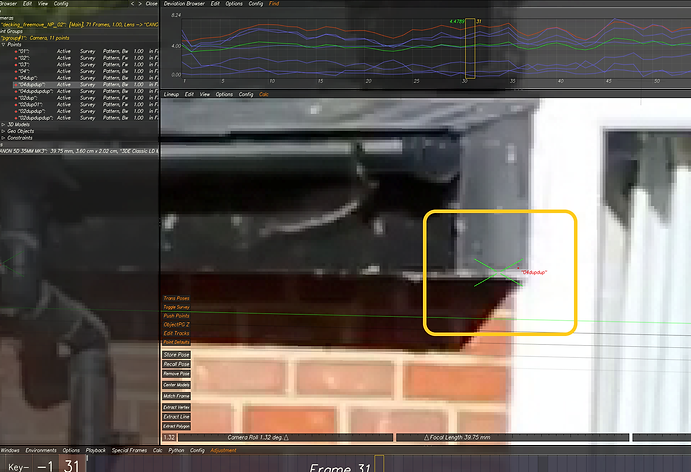
To check the tracks, go to Lineup view and see if the red dot is placed in the middle of the green cross. If not, rectify the track.

I made three tracking points on the wall to make the tracking even more precise. Then I needed to align those points with the survey points I already made for the wall.
Converted the wall tracking points to survey points.

Used Push Points Tool to align the points.
Assignment 01: 3D Match Moving Project
For the first assignment, I was given a video and a survey image to work on and do 3D match moving by using 3D Equaliser and Nuke.
For the assignment, I had to:
1- have a minimum of 40 tracked points
2- get a low deviation
3- use survey data
4- add locators and 3D Cube
5- export camera, LD data, locator geo, and 3d models to Nuke
6- undistort lens and reformat
7- place a cleanup patch on the fire exit sign
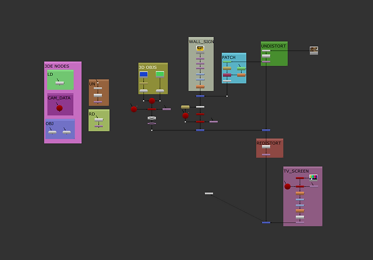
I tried to do whatever the assignment had asked me, then moved on to the next level and added a tv screen (colour bar) and a sign above the door by using the tracking data I had brought into Nuke from 3DE. Below you can see my developmental work.
Development #1:
Here I did everything the assignment had asked me.
Development #2:
I put a colour bar image on the left-hand TV and used the 3DE info I'd brought into Nuke.
Development #3:
Added a sign above the door.
Node graph
.png)
Screen recording (3DE)
Screen recording (Nuke)
Week 07: Shooting footage for assignment 02
We went to the studio this week to shoot footage for the second assignment.
Week 08: Surveys (part 2)
We continued to explore how to use various survey data in 3DE to solidify our tracking process this week. We had a look at how to import multiple reference images into 3DE and track points across the reference images and our footage.

3DE4 -> File -> Import -> Import Multiple Reference Frames... v1.1
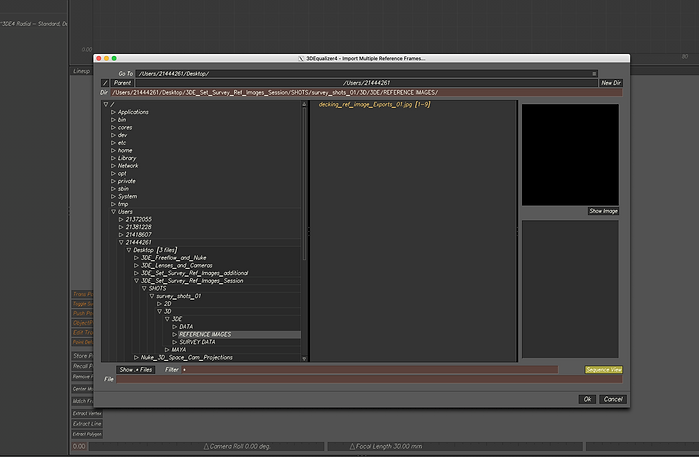
Navigated to where the reference images are and imported them into 3DE.

Deleted DS_Store camera as we don't need that.

We need to have a lens for our footage and another for our ref images.

Reference lens set up.

Footage lens set up.

Assigning lenses to the cameras.

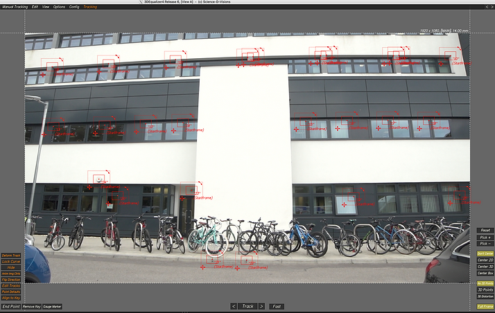
I made more than 40 tracking points and shared them across the ref images and the main footage.
Week 9 Lens Distortion and Grids
This week, we learnt how to use a grid to have a more precise lens distortion set up in 3D Equaliser. First, we were given a grid shot that was filmed for the purpose of lens distortion. Then, we brought the grid shot into 3DE as a reference camera and calculated the lens distortion based on that.

Lens attributes set up.
About 30 tracking points added.

Made a camera constraint since the shot is not freemove, is nodal.

Used a camera constraint.

Chose 3DE Radial as the lens distortion model.
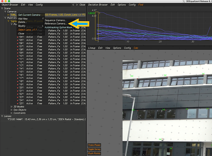
Brought it the grid shot as a reference camera.

Grid shot selected.
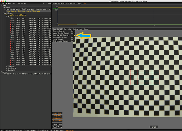
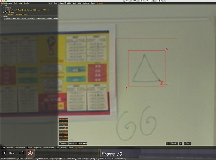
Changed the viewer to Distortion Grid Controls.
Aligned some points with the checkerboard. Pressed Snap to have 3DE align the others points for us.

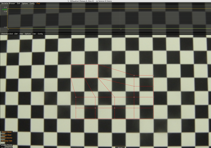
Expanded the points to cover the whole grid.
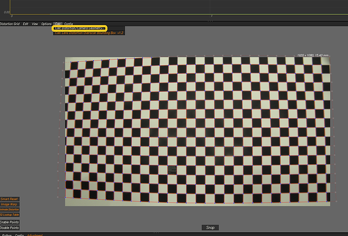
Finally calculated the lens distortion based on the grid we brought in.

Calc lens distortion window.
Week 10: Nuke Maya Pipeline
I looked at how to take tracked footage from 3DE to Maya this week. In Maya, I learned how to prep the software to bring in my assets, set up the size of the image sequence correctly and add a 3D object to the scene. Before that, I applied lens distortion data to the image sequence in Nuke in order to undistort my footage for Maya.
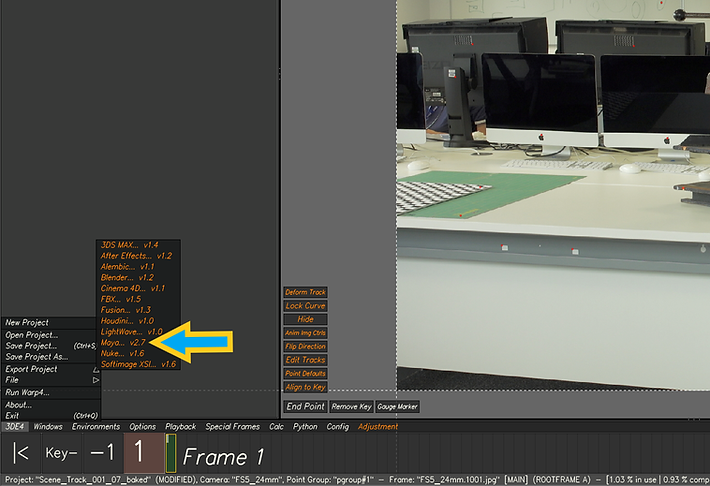
In 3DE, I tracked the footage. Next, I needed to export Mel script and lens distortion files. Note: Make sure to set the start frame to 1001 when exporting.

Undistorted the sequence as above.

Named the undistorted sequence appropriately.

Tick "Use Image Sequence". Change the sequence to the undistorted footage.

I needed to scale up the image plane as well as film back size by using a simple python code as shown above.
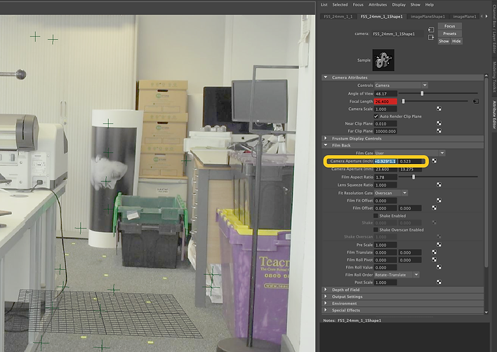
Film back size set up.

Here I wanted to add a sphere to the scene. To have the shadows of the sphere, I made a plane and assigned aiShadowMatte to it.

Added an Area Light and turned off Normalize.

Set up the image size in the Render Settings window. The resolution of my footage needed to be multiplied by 1.1.
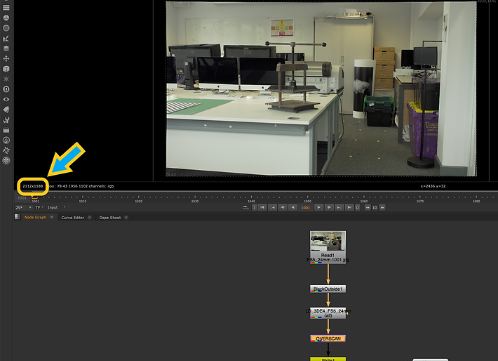
I could also find the correct image size (after scaling up) by going back to Nuke and clicking on the Overscan node.

I disabled the image plane when rendering the sequence as I wanted to comp the sequence in Nuke.

Render Settings set up.

Rendered out beauty (RGBA), specular and shadow passes to be able to composite them in Nuke.
Comping CG back in Nuke (2 methods)
.png)
Using Shuffle node
.png)
Assignment 02
Above is the original footage I shot for the second assignment.
I tracked the scene in 3DE using various techniques, and then exported and brought the tracking data into Nuke.
All markers are cleaned. Scene is ready for green screen removal and adding 3D assets in Maya.

Above is my mech character I am going to put it in the scene right in place of the blue cube.
Note: The whole process of modelling, texturing, rigging, and so on is done by me.
I removed the green screen and used different motion capture data for my mech characters in the scene. Used multiple lights as well as 3D assets in the scene, and a bit of Python code to animate my main spotlight.
Here I have added smoke to the scene, and most importantly, I colour-graded the lights and the reflections on the characters. I also added lens dirt and used the red colour all over the scene to emulate the feeling of being in a nightclub. However, there are still a few problems that I will work on them. For instance, the table needs to be roto'ed to be placed in front of the 3D background.
Next, I played around with light groups and AOVs. I also used a bit of Python code to make flashing lights in the scene. Different render passes were used to add more life and attraction to the sequence. For instance, I defocused the background using the Z Depth channel. Also, I changed the colour and intensity of some of the lights in the scene.
Note: My Maya sequence was rendered with relatively low sampling rates because my computer could not handle a higher sampling quality. As a result, the rendered sequence seems noisy. I will try to render my Maya file by another machine as soon as possible and put it here.
I used a better quality Arnold rendered sequence here. Also, I made a few adjustments and changes, such as refining roto edges, redoing the green screen removal process, etc.
Final result
Video with sound.
FINAL DEVELOPMENT WITH SOUND.
NOTE: While I tried very hard to be as creative as possible and am happy with the result, I believe there is still room for improvement. Render quality still needs to be improved, and I will further work on a few details of my scene during the summer.
Screen recording from inside Maya and Nuke
VFX Breakdown
Video with sound.